Improvised: Dummy load
So I was in need of a small dummy load that can handle a few watts to test a small SMPS. I couldn’t wait until the holidays and the following weekend were over so I had to improvise something using components I had laying around. As I stopped etching my own PCBs at home I had to go old-school and build everything using a prototyping board. I’m quite happy with how the result turned out.
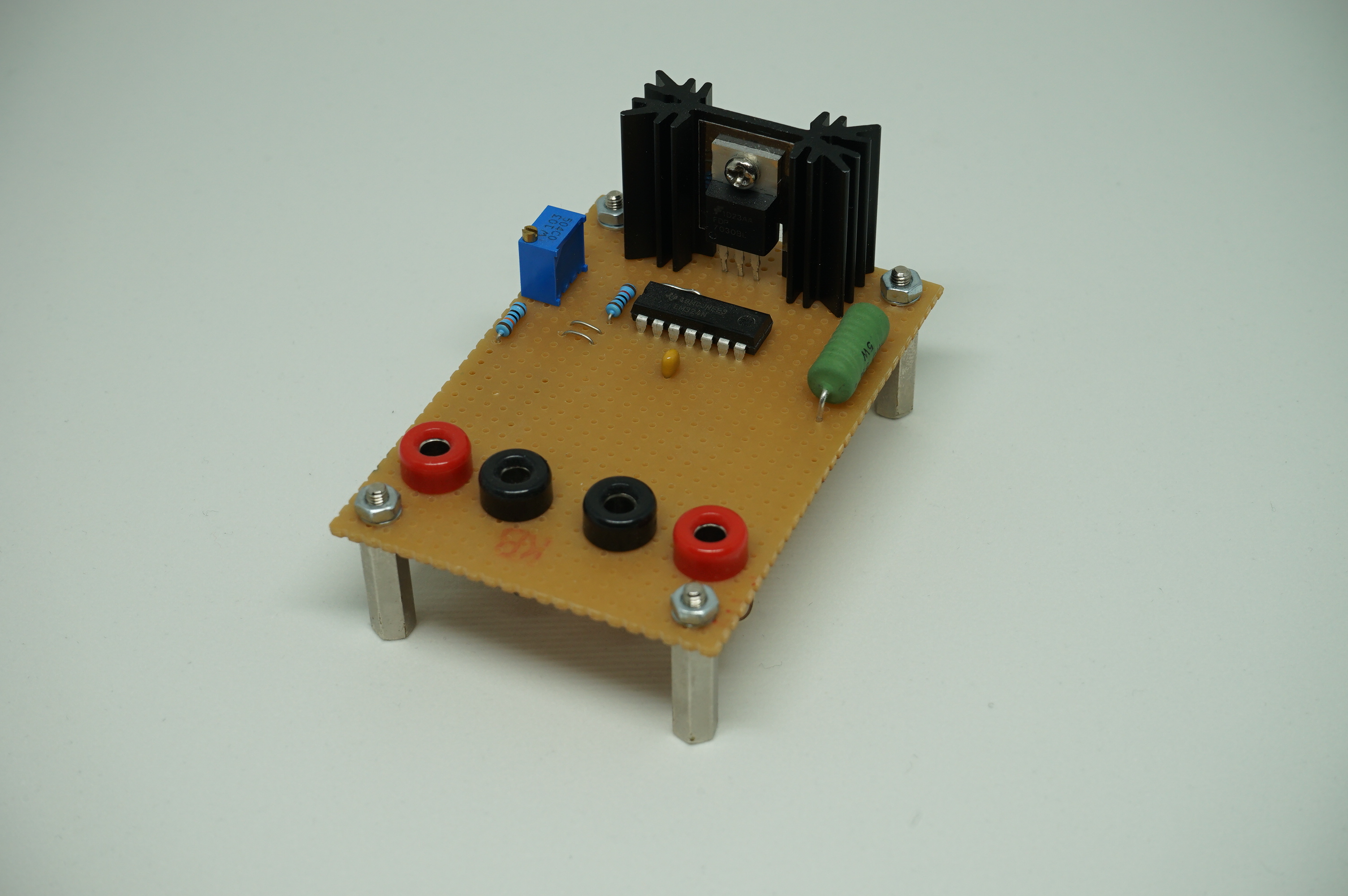
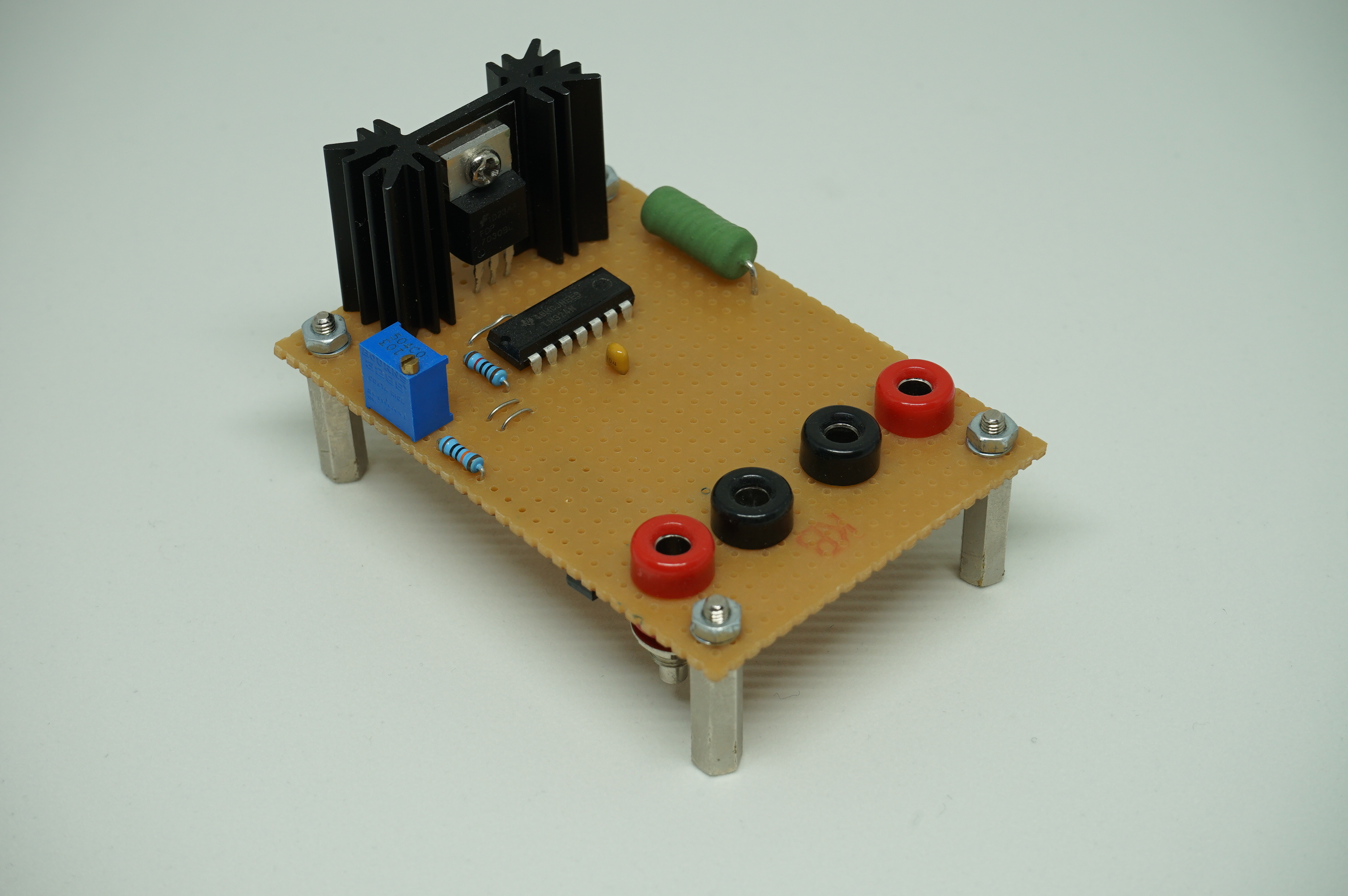
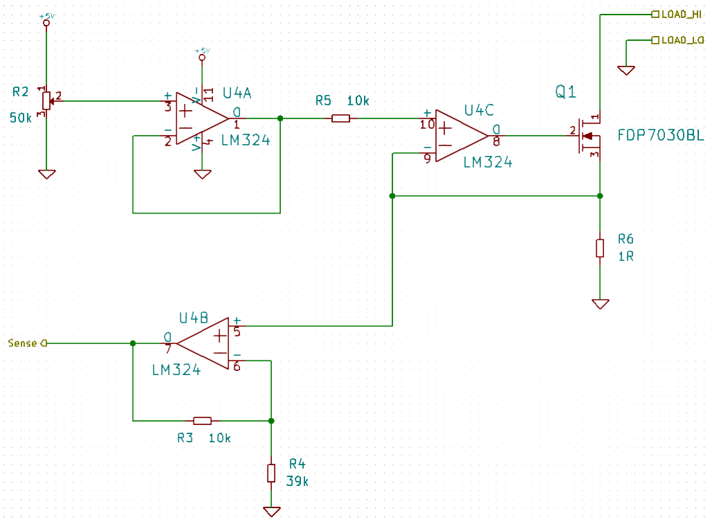
The circuit is very common and nothing special at all. The core of the circuit is a MosFET which is deliberately held in a semi-conductive state. A 10-turn potentiometer and a couple of OpAmps are used to control the gate voltage and therefore the current flowing through this dummy load. The shunt resistor R6 should probably be lower to decrease the voltage drop across the dummy load but I only had 1 ohm power resistors lying around. However, the nice benefit of this is that the voltage drop across the resistor doesn’t need to be converted to retrieve the current going through the load.
Note that this is a purely resistive DC dummy load. Furthermore, this load may not be used for AC signals due to the fact that we’re using a MosFET which only works in one direction.
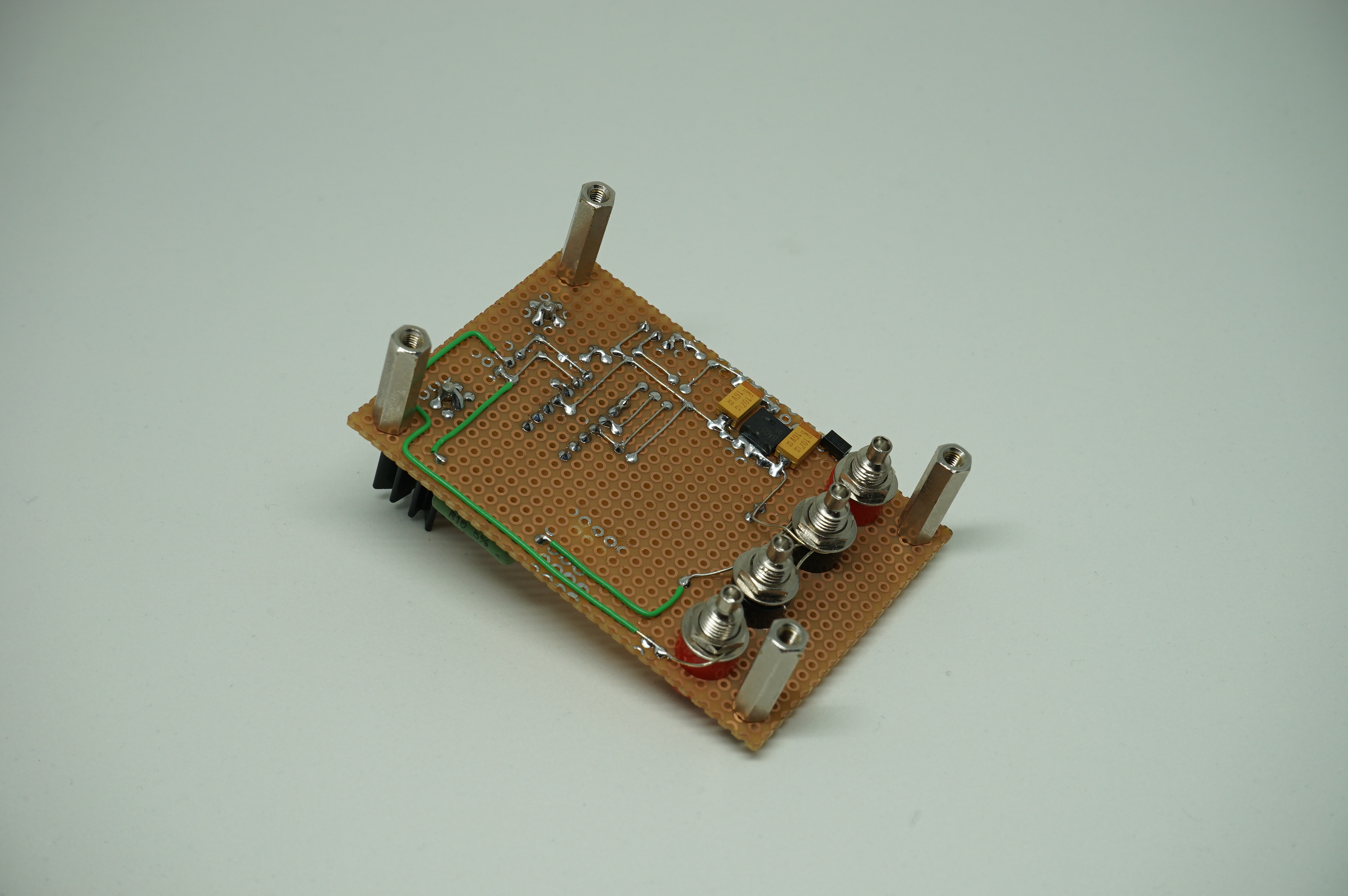
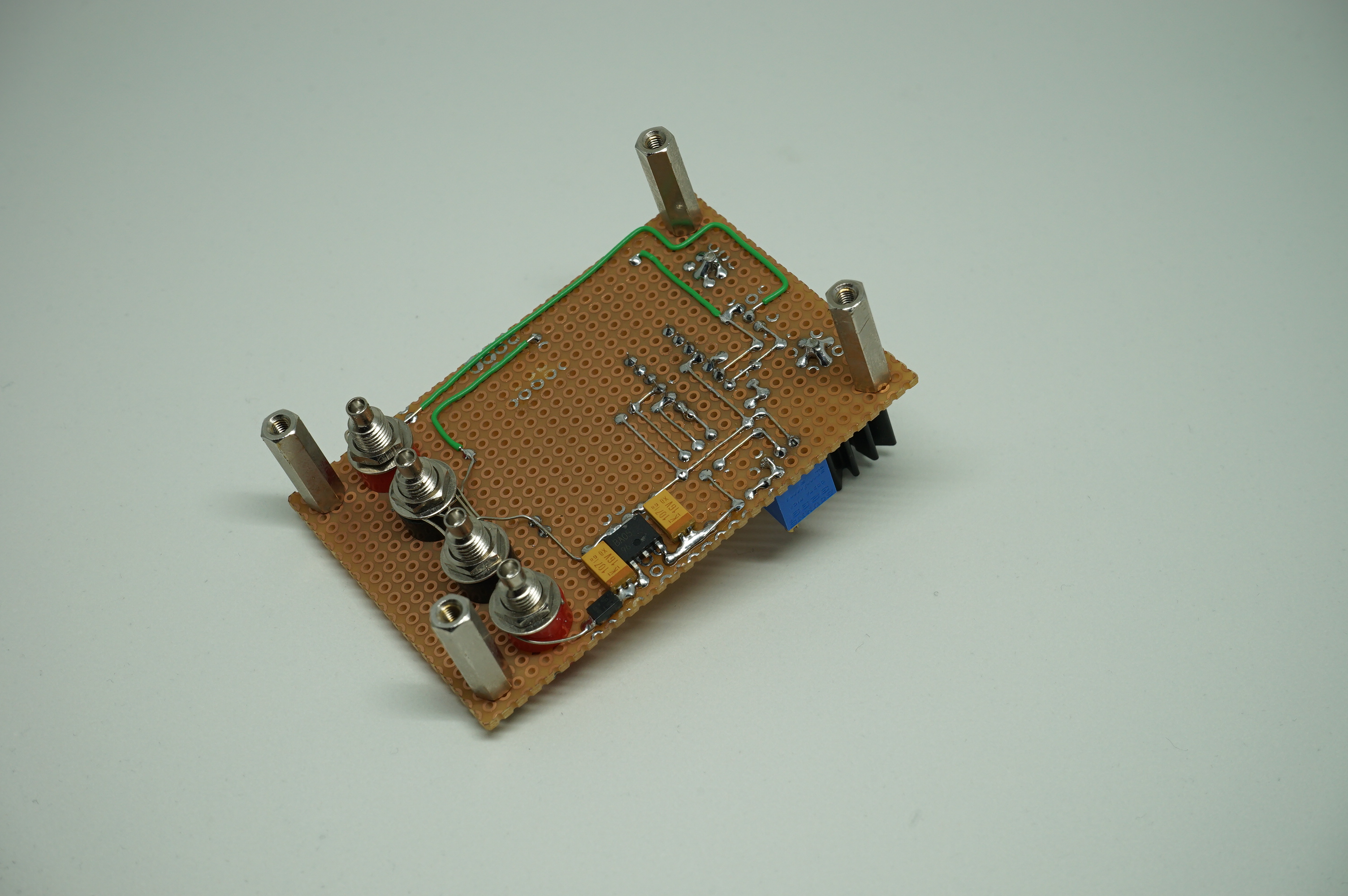
I didn’t have a through-hole voltage regulator around for the +5V rail of the OpAmps so I had to put some SMD components on the solder-side of the prototyping board. One of the 4mm connector pairs is for the power supply, the other pair is to connect the load itself.
For what I needed it this little device performed very well. I don’t really have needs for a professional dummy load but I might create a second version of this one with a proper enclosure at some point. Maybe even a fancy touchscreen?